
In this section I will try to explain in several steps how I prepare and
assemble the chassis and engine parts for a single car. I usually do the
majority of the chassis first and then the engine (this gives the chassis
parts that help hold the engine in place a chance to dry more than if you
do the engine first and also shortens the time you wait before installing
the engine!) PLEASE NOTE: that I will not always follow the instruction
sheet but I will use the part names in the sheet (these names are from a
1997 Monte Carlo sheet other kits may be different).
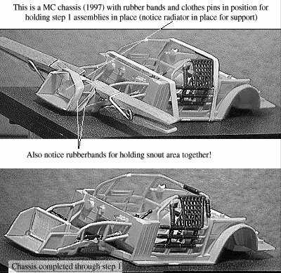
You will need some rubber bands and clothes pins here. The rubber bands I
use are from broccoli bunches from my local supermarket (they are about 2" in
diameter and 1/4 to 5/16 wide!)
IMPORTANT NOTE!!! You must go over all of the parts you are going to
assemble and scrape the paint from the points where the parts are to be
glued. I will list all of the parts in each step... scrape the parts on
the step before beginning assembly! Also to aid in determining where
these points will be you may want to look ahead in the kit inst. sheet to
see what will be attached to these parts and where so you won't have to try
to do it with the parts on the model!!!
Do this first: Remove the part of the parts tree around the front of the
"frame" this will be used later to make the "Earnhardt bar" (this part is
not in the kit) if it is a 1997 or later car! (I have these pieces from all
the 1997 MC and Pontiac kits I've done and will use them as needed for any
kit I build MC, Thunderbird or Pontiac!).
Step 1
Parts list: "upper arms", "frame", "pedals", "firewall", "cage side"left
and right, "roll bar", "steering shaft', "stiffener brace", "stiffener
bar", "seat", "shifter". Remember to remove paint from gluing points on
these parts before starting assembly!!!
First assemble the cage sides and the roll bar and fire extinguisher and
set them aside to dry. Next follow step 2 A and B in the instructions.
Jump to part 3 C and D. Note: before glueing the seat to the floorpan
apply the little seat manufacturer decals to the headrest and then cut out
the 5 point harness trimming as close to the decal as possible. Then glue
the 5 point harness to the seat using clear craft glue! This will give
the belts a more realistic look (they won't look painted on!!) Also one
note regarding T-Bird kits: Since the radiator and oil cooler are one piece
they must be glued on at this point!!! (the attachment point between them
must go between the frame and the cage front end!) At this point the cage
sides/rollbar assembly is probably dry enough to attach to the frame. If
you haven't made sure all of the mating surfaces between the frame and
these parts have the paint removed from them do so now! Alright first
apply glue to the sides of the frame where the cage sides will meet it, the
sides of the firewall, and the areas where the cage and frame front ends
meet (including the little grooves just behind where the radiator sits!)
Then take the cage/rollbar assembly and lower it over the seat and spread
it apart at the front until it sits down on the frame. Note: you may have
to spread the rear a little to get it to go down! Immediately apply one
rubber band at each end of the assembly (one across the top of the "roll
bar" and one at the firewall") make sure all parts are aligned at these
areas. Then carefully align the front of the cage frame parts and use
clothes pins to hold them together and also place
the "radiator" (don't glue it!!!) in it's place in the chassis front and
wrap a rubber band around the snout and radiator to hold it all together. (if necessary, no two kits are alike
some require this some don't!). This ends step 1. Allow this assembly to
dry over night! Picture of Completed Step 1
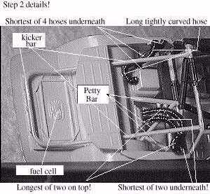
Step 2
Parts list: "stiffener bar", "petty bar", "hose"s (cockpit air inlet).
"rear shelf", "kicker bar assembly". Remember to remove paint from
contact points!!!
You may now remove the rubber bands from the frame rollbar cage
assembly! Follow step 3 F-H and J in the kit instruction sheet.
Picture of Completed Step 2
Step 3
Parts list: "oiler tank", "shock assembly" rear, "spring"s, "arm assembly",
"rear axle""front axle"(go together to form rear axle), "pump belt",
"coolant pump", "inner wheel" (2), "outer wheel"(2).
I am going to deviate from the kit instructions here. I always clean
the paint from the ends of the "rear axle" and also clean up the small
molding ridges that are left behind (I wire my models down most of the time
so this may seem pointless) so that when I push the inner wheels on in this
step they will "roll" freely. I then press one "outer wheel" in to each of
the two tires for the rear and then press the "outer wheel"tire assemblies
onto the two "inner wheel"s. Now follow step 4 A-D in the kit
instructions (I cannot stress this enough make sure that ALL contact points
are clean of paint because this is what lines up and holds the rear end in
place solidly!!!) Picture of Completed Step 3
Step 4
Parts list: Parts from step 1 in the instruction sheet (engine parts),
"exhaust pipes", "drive shaft", "frame braces", "steering column",
"steering shaft", "dashboard top", "dashboard front".
Follow step 1 A-C allow the engine to dry for several hours... while the
engine is drying paint the gauges on the dash with aluminum paint, then
assemble the dash and steering (per step 5 in the kit instructions) and
set aside to dry ... then once the engine is dry follow step 4 E-G in the
kit instructions.
Step 5
Parts list: "top stiffener bar", "top brace", "mirror", "fan shroud",
"radiator", "upper hose"(radiator), "lower hose"(radiator), "shock
assembly"(front), "lower arms", "inner wheel"(2), "outer wheel"(2).
Follow step 3 I of the kit instructions and if necessary put a rubber
band around the assembly to hold it together. Note: On the T-Bird kits
the "top stiffener bar" is made to fit diagonally from one corner of the
cage to the other but I usually cut it off just behind the padding and
install it in the center parallel to the side top bars! While allowing the
last assembly to dry work on the "lower arms"/front wheels assembly. Again
making sure all contact points are clean for assembly (especially where the
"lower arms" and the "frame" and the "upper arms" contact ... this is what
holds and aligns the front end of the model)!!! Take the "lower arms" and
again clean the paint from the ends of the spindles and also clean up the
small molding ridges that are left behind as you did on the rear axle!
Again snap the "inner wheel"s onto the "lower arms" and assemble the "outer
wheel"s and tires. Push the "outer wheel" tire assemblies onto the "inner
wheel"s and set aside! Next glue the "fan shroud" and "radiator" together
and then glue this assembly to the front of the frame. Next glue in the
"upper hose" and "lower hose" (radiator) and then the "shock assembly".
Lastly glue the "lower arms" wheels and tires assembly in place making sure
all contact points are aligned once the glue has set for a few minutes you
can turn the completed chassis over and the weight of the chassis will keep
the front suspension in place!
Step 6 Final step!!!
If the model you are building is a 1997 or later take the part of the
parts tree that I told you to save for the "Earnhardt bar" I take and heat
this piece with a candle just until it will bend but not distort and bend
it to an angle close to that of the windshield and then cut it off about an
eighth of an inch from the bend at one end and then cut it a little longer
than needed to reach the "top brace" and adjust the length until it fits
and Glue it into place! On some cars this bar is bare and is the same
color as the chassis on others it has padding over it! Now is a good
time to apply the wheel and tire decals!!! Well that's it!!! You're
probably saying YIKES!!!!! But you won't believe how good it all looks
when you get done!!!
To Go Back To The Model Center Click Here